
Factory utility planning
Bottling Line Utility Consumption Planning
Turn separate machine data sheets into one operating-state utility schedule that the factory and project team can actually design around.
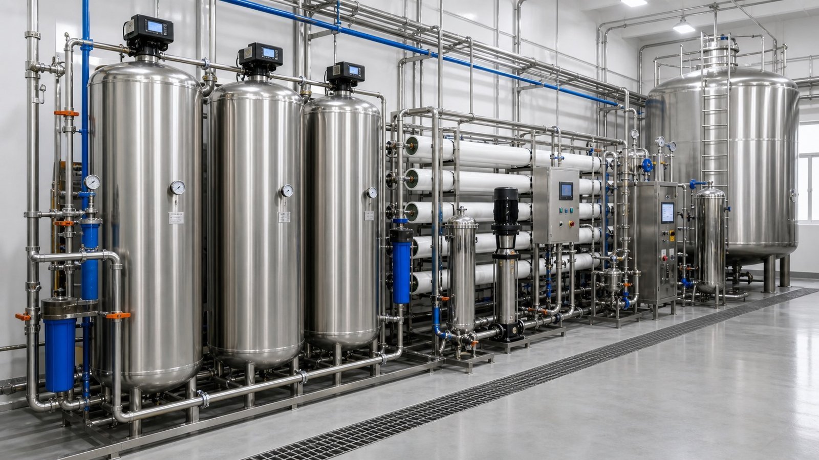
Published by Allot Tech. Project contact: founder Mr Kcal. Final engineering, performance, materials, compliance, manufacturing responsibility and commercial terms must be confirmed for the selected resource and signed project scope.
Updated September 3, 2026Direct answer
Utility design needs operating states, not one total number.
A bottling line utility schedule should separate connected load, normal operating demand and peak demand for each production state. Collect machine-level power, compressed air, process and rinse water, cooling, steam or heat, chemicals and drainage data on the same product and output basis. Then add common systems, distribution losses, simultaneous operation, start-up and cleaning states, future loads and buyer-supplied interfaces. Do not add every nameplate value and call the total a realistic operating demand.
Project definition
Start with the complete decision basis.
Blowers, compressors, chillers, heaters, pumps, fillers, conveyors and packers do not draw utilities in the same pattern. Production, start-up, cleaning, sterilization, changeover and standby can create different peaks. The factory designer needs a traceable schedule with source documents, units, conditions, diversity assumptions, connection points and design margins. Final sizing and local compliance remain with qualified utility and building professionals.
Production basis
Product, package, output, number of lines, shifts, cleaning plan, simultaneous equipment and future expansion.
Machine schedules
Connected and operating power, pressure, flow, temperature, quality, return condition and source revision.
Site conditions
Voltage, frequency, ambient range, elevation, source-water condition, utility pressure, drainage and discharge limits.
Operating states
Start-up, normal production, stop, changeover, CIP, SIP where applicable, shutdown and maintenance isolation.
System or development path
Build the schedule from each equipment user to the factory source and return.
Inventory users
List every machine, process skid, common utility package and buyer-supplied user with a controlled tag.
Normalize units
Convert vendor data into agreed electrical, flow, pressure, temperature, quality and time units without losing source values.
Map operating states
Mark which users run together during production, start-up, cleaning, sterilization, changeover and standby.
Apply diversity carefully
Use documented simultaneity and cycling assumptions rather than an unexplained percentage reduction.
Design distribution
Include headers, pressure drop, cable and transformer capacity, cooling return, drains, treatment and metering points.
Measure and reconcile
Compare actual demand at commissioning with the approved basis and update operating and maintenance records.
Quotation comparison
Make every utility figure traceable to a condition and project boundary.
| Decision area | Buyer should provide | Proposal should clarify |
|---|---|---|
| Electrical load | Available supply and expansion plan. | Connected kW, running kW, starting method, power factor, simultaneity and panel boundary. |
| Compressed air | Available pressures, quality and room plan. | Flow by pressure level, peaks, treatment, receivers, recovery, pressure drop and standby. |
| Water and drainage | Source and discharge conditions. | Flow, quality, temperature, recovery, peak drains, chemical content and treatment responsibility. |
| Heating and cooling | Available steam, hot water, chilled or cooling water. | Duty, temperature approach, flow, return condition, peaks, control and excluded generation equipment. |
| Acceptance metering | Required operating evidence. | Meter points, instruments, calibration, stabilization period, data log and reconciliation method. |
Solve the next project problem
Close these proposal gaps before price becomes the decision.
Use the brief below to turn a vague supplier conversation into questions that can be answered and documented.
Make this decision comparable.
Send: Available supply and expansion plan.
Require: Connected kW, running kW, starting method, power factor, simultaneity and panel boundary.
Make this decision comparable.
Send: Available pressures, quality and room plan.
Require: Flow by pressure level, peaks, treatment, receivers, recovery, pressure drop and standby.
Make this decision comparable.
Send: Source and discharge conditions.
Require: Flow, quality, temperature, recovery, peak drains, chemical content and treatment responsibility.
Send the beverage, package files, required output, factory conditions, destination and current project stage. The Allot Tech Project Desk can help organize the first comparison.
Decision evidence
Keep the utility design connected to vendor data and operating reality.
Evidence should be identified before the order or approval stage so both sides know what will support the next decision.
Utility source register
Link every schedule value to an equipment tag, vendor document, revision, condition and responsible reviewer.
Operating-state matrix
Show simultaneous users and peak contributors for production, start-up, cleaning and other states.
Distribution calculation set
Record pressure drop, cable and transformer basis, pipe sizing, return conditions, drains and design margins.
Commissioning reconciliation
Compare planned and measured demand with product, output, ambient condition and unresolved differences.
Separate nameplate, normal and peak demand
Nameplate or connected load helps size protection and distribution, but it does not describe energy use or every coincident peak. Keep the three values separate and explain cycling, start-up and diversity.
- Preserve original vendor data
- State the operating condition
- Identify the actual peak contributors
Include cleaning and non-production states
CIP, heating, sterilization, bottle change and start-up can shift demand away from normal production. A factory designed only around steady running may still fail during transitions.
- Map each state and duration
- Check drain and heating peaks
- Define restrictions on simultaneous operation
Meter the users that drive uncertainty
Commissioning meters help reconcile supplier estimates with site conditions and support later loss reduction. Place them where the line, utility package and shared factory demand can be distinguished.
- Agree meter locations before installation
- Record instrument range and calibration
- Update the utility schedule after testing
Decision gates
Move forward when the next commitment has enough written evidence.
Project stages overlap, but each commercial commitment should have a visible basis, named approvers and a list of unresolved items.
Engineering basis approved
The product, package, output, equipment boundary, layout, utilities, responsibilities and open assumptions are controlled.
Manufacturing and test basis approved
Drawings, component schedule, test materials, acceptance conditions, documents and planned evidence are agreed.
Delivery and handover released
Punch-list closure, packing, shipment files, site readiness, installation scope, training and support ownership are visible.
Before requesting a proposal
Build one brief that every resource can answer on the same basis.
This page is designed to help an international buyer prepare a clearer discussion, not to replace the responsible resource’s engineering or the buyer’s professional review.
Product
Beverage, process, hygiene, shelf-life and operating conditions.
Package
Container, closure, label, code, finished pack and approved files.
Output
Required rate for a named format, shifts, annual plan and changeovers.
Factory
Measured space, utilities, access, drainage and local site constraints.
Project scope
Equipment boundary, documents, FAT, delivery, startup and destination.
Allot Tech organized recurring buyer questions, project-scoping patterns, available catalog inputs and specialist-resource context into a decision sequence. No customer case, certification, output guarantee or factory ownership is implied unless separately verified for the named project.
Reference basis
Primary and specialist sources used to frame the buyer questions.
These sources support definitions and planning context. The current edition, local requirements and project-specific acceptance criteria still need confirmation by the responsible parties.
- Atlas Copco – PET Blowing High-Pressure Air
Specialist context for pressure, flow, air quality and continuity as distinct utility decisions.
- Sidel Empty Container Air Conveying
Official equipment context showing speed-responsive airflow and package dimensions as line utility inputs.
Manufacturing context
Use equipment views to ask more specific project questions.
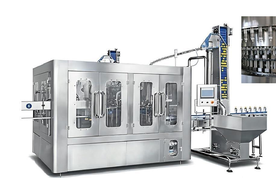
The process illustration supports scope discussion. The XGF equipment image is reproduced from page 9 of the Allot Tech 2026 catalog; use the catalog and project documents to review the applicable configuration.
Buyer questions
Frequently asked questions
What utilities does a bottling line normally need?
Depending on scope, it may need electrical power, several compressed-air levels, process and rinse water, chilled or cooling water, steam or hot water, chemicals and drainage.
Is connected load the same as operating consumption?
No. Connected load is a design input; normal and peak operating demand depend on equipment states, cycling, output and simultaneity.
How should suppliers state utility consumption?
Ask for value, unit, pressure or temperature, quality, operating condition, output basis, peak duration, connection point and included generation equipment.
Who sizes the factory utilities?
Qualified site and utility professionals should complete final design using approved supplier schedules and local requirements.
Project discussion
Build a Bottling Utility Schedule
Send the beverage, package files, required output, factory conditions, destination and current project stage.