
Factory readiness planning
Bottling Line Layout & Utility Planning
Turn the equipment list into a dimensioned factory plan with product flow, service access, drainage, utilities, logistics and future-change assumptions.
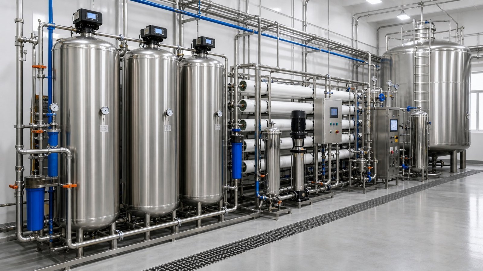
Published by Allot Tech. Project contact: founder Mr Kcal. Final engineering, performance, materials, compliance, manufacturing responsibility and commercial terms must be confirmed for the selected resource and signed project scope.
Updated September 3, 2026Direct answer
Factory readiness and equipment engineering must move together.
A layout should begin with a measured building and a complete process flow, then place equipment around safe access, operator movement, material routes, drains, utility headers, maintenance clearances and shipment or installation access. The buyer should not approve a decorative floor plan alone. A useful layout has dimensions, elevations where needed, equipment and conveyor references, utility connection points, loads, interface ownership and a revision history tied to the approved equipment list.
Project definition
Start with the complete decision basis.
Civil work often starts while equipment is being manufactured. If machine dimensions, drainage, floor loads, utility demand or access assumptions change without controlled revisions, the site may be ready on paper but not ready for installation. The layout process should therefore connect supplier drawings with the buyer, local architect or contractor, utility specialists and installation team. Local codes and final engineering remain the responsibility of qualified parties appointed for the project.
Building survey
Internal dimensions, columns, doors, floor levels, ceiling, obstructions, loading access and available expansion area.
Process flow
Raw materials, water, ingredients, containers, packaging, people, waste, finished goods and cleaning routes.
Utility conditions
Voltage, frequency, power capacity, compressed air, water, steam, cooling, drainage and discharge limits.
Operating plan
Products, formats, output, shifts, sanitation, staffing, maintenance access and future equipment priorities.
System or development path
Develop the site package from measured room to approved connection schedule.
Survey the building
Confirm coordinates, clear heights, columns, pits, doors, floors, drains, routes and installation openings.
Place the process
Arrange treatment, preparation, packaging, storage and cleaning around product flow and hygienic separation needs.
Check access
Reserve operator aisles, maintenance pull space, platforms, lifting routes, emergency access and material movement.
Map utilities
Show connection location, demand, quality, pressure, temperature, pipe or cable route and responsible party.
Coordinate civil work
Transfer machine loads, foundations, trenches, drains, penetrations and elevations to qualified local designers.
Control revisions
Keep approved equipment, layout, utility schedule and site changes aligned through installation and commissioning.
Quotation comparison
Review more than the footprint before approving a bottling-line layout.
| Decision area | Buyer should provide | Proposal should clarify |
|---|---|---|
| Building fit | Accurate survey and installation constraints. | Overall dimensions, elevations, service envelope, doors, routes and unresolved clashes. |
| Product flow | Material receiving and finished-goods plan. | Direction, accumulation, hygiene zones, rejects, waste and warehouse handover. |
| Utilities | Available capacity and quality at site. | Demand by machine, diversity basis, connection points, pipe sizes and buyer work. |
| Civil interfaces | Local engineering and code requirements. | Loads, drains, pits, foundations, platforms, penetrations and release drawings. |
| Change control | Named approvers and construction schedule. | Drawing register, revision cloud, approval status and effect of late equipment changes. |
Solve the next project problem
Close these proposal gaps before price becomes the decision.
Use the brief below to turn a vague supplier conversation into questions that can be answered and documented.
Make this decision comparable.
Send: Accurate survey and installation constraints.
Require: Overall dimensions, elevations, service envelope, doors, routes and unresolved clashes.
Make this decision comparable.
Send: Material receiving and finished-goods plan.
Require: Direction, accumulation, hygiene zones, rejects, waste and warehouse handover.
Make this decision comparable.
Send: Available capacity and quality at site.
Require: Demand by machine, diversity basis, connection points, pipe sizes and buyer work.
Send the beverage, package files, required output, factory conditions, destination and current project stage. The Allot Tech Project Desk can help organize the first comparison.
Decision evidence
A practical site-readiness package for installation planning.
Evidence should be identified before the order or approval stage so both sides know what will support the next decision.
Approved general arrangement
Dimensioned equipment, conveyors, access, flow direction, utilities and revision status on one controlled plan.
Utility consumption schedule
Demand and connection data by equipment, including stated operating condition and supplier or buyer responsibility.
Civil interface register
Foundation, floor load, drain, trench, platform, opening and lifting requirements assigned to qualified parties.
Readiness walkdown
Photographs and signed status for room access, floors, drainage, utilities, lighting, safety and material availability.
Use dimensions that can be built
A machine footprint without service doors, control-cabinet clearance, platform access or component-removal space can create expensive site changes. Key elevations, maintenance envelopes and installation routes should be reviewed with the same care as line length and width.
- Show columns, doors and clear height
- Reserve maintenance and lifting space
- Verify the heaviest or largest installation route
Separate demand from connection conditions
Installed power is not the same as normal demand, and compressor nameplate capacity is not proof that the required pressure and air quality will reach the machine. Each utility should have a stated operating basis, connection point and responsible party.
- Record pressure, temperature and quality
- Identify peak and normal demand assumptions
- Confirm local distribution and isolation scope
Release civil work against controlled drawings
Supplier drawings inform foundations, drains and utility routes, but qualified local professionals should verify code, structure and site safety. The project register should make clear which drawing revision was used for construction and how later changes will be handled.
- Use an approval and revision register
- Photograph concealed work before closure
- Recheck the site before equipment arrival
Decision gates
Move forward when the next commitment has enough written evidence.
Project stages overlap, but each commercial commitment should have a visible basis, named approvers and a list of unresolved items.
Engineering basis approved
The product, package, output, equipment boundary, layout, utilities, responsibilities and open assumptions are controlled.
Manufacturing and test basis approved
Drawings, component schedule, test materials, acceptance conditions, documents and planned evidence are agreed.
Delivery and handover released
Punch-list closure, packing, shipment files, site readiness, installation scope, training and support ownership are visible.
Before requesting a proposal
Build one brief that every resource can answer on the same basis.
This page is designed to help an international buyer prepare a clearer discussion, not to replace the responsible resource’s engineering or the buyer’s professional review.
Product
Beverage, process, hygiene, shelf-life and operating conditions.
Package
Container, closure, label, code, finished pack and approved files.
Output
Required rate for a named format, shifts, annual plan and changeovers.
Factory
Measured space, utilities, access, drainage and local site constraints.
Project scope
Equipment boundary, documents, FAT, delivery, startup and destination.
Allot Tech organized recurring buyer questions, project-scoping patterns, available catalog inputs and specialist-resource context into a decision sequence. No customer case, certification, output guarantee or factory ownership is implied unless separately verified for the named project.
Manufacturing context
Use equipment views to ask more specific project questions.
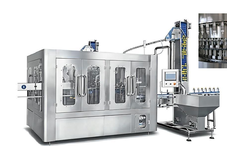
The process illustration supports scope discussion. The XGF equipment image is reproduced from page 9 of the Allot Tech 2026 catalog; use the catalog and project documents to review the applicable configuration.
Buyer questions
Frequently asked questions
What files are needed for a bottling line layout?
Provide a measured building drawing, equipment scope, container and pack flow, utilities, access restrictions, warehouse handover and any local civil or hygiene requirements.
Should utility points appear on the layout?
Yes. A coordinated plan or linked schedule should identify each connection location, demand, condition and responsibility so site contractors can prepare the correct services.
Who confirms foundations and floor loading?
Equipment resources provide loads and interface information, while qualified local structural and civil professionals should confirm the final design and compliance for the site.
When should the site-readiness review occur?
Review during layout approval, again before equipment shipment, and once more before installation personnel mobilize. Open items should have owners and target dates.
Project discussion
Discuss Layout and Utility Planning
Send the beverage, package files, required output, factory conditions, destination and current project stage.